


"The core hydraulic principles every field mechanic needs are: Pascal's Law (pressure transmission), the pressure–force–area relationship, flow vs. speed, fluid viscosity, contamination control, and safe depressurisation practices.
Why the Fundamentals Matter in the Field
When you're lying on your back under an excavator in the mud, troubleshooting a cylinder that won't hold position, textbook theory can feel a long way from reality. But the truth is that every symptom you encounter in the field — sluggish movement, overheating, erratic control, unexpected noise — traces back to a handful of fundamental principles. Understanding those principles is the difference between swapping parts until something works and diagnosing the real problem on the first attempt.
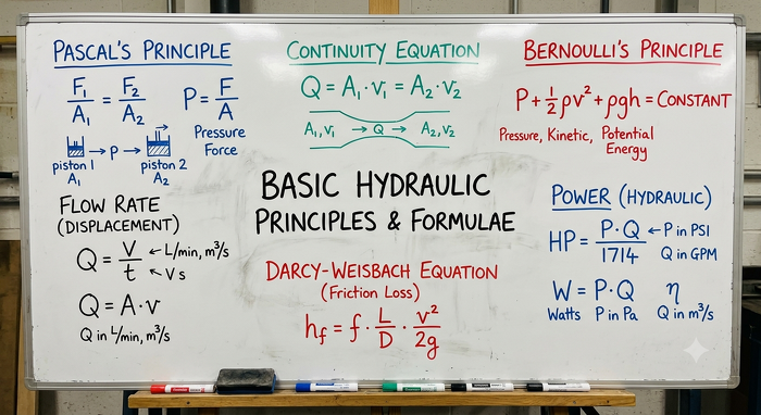
This post covers the core hydraulic concepts that matter most to field mechanics. We've kept the maths light and the practical application heavy. Whether you're new to hydraulics or have been turning wrenches for twenty years, a sharp grasp of these basics will save you time, money, and frustration on every job.
1. Pascal's Law — The Foundation of Everything
Every hydraulic system on the planet rests on a single principle discovered by Blaise Pascal in the 17th century: pressure applied to a confined fluid is transmitted equally in all directions throughout that fluid. That's it. That one sentence explains why a small hand pump can lift a 20-tonne load.
In practical terms, when a pump pressurises oil inside a closed system, the pressure is the same at every point — at the pump outlet, at the valve block, at the cylinder port, and in every millimetre of hose in between (minus any friction losses). This is why you can take a pressure reading at a convenient test point and trust that it reflects what's happening across the whole circuit.
Field tip: If your gauge reads 200 bar at the pump, but the cylinder can't develop enough force, the pressure isn't "disappearing." Look for a leak path — an internal bypass in a worn valve, a blown seal in the cylinder, or a relief valve that's set too low and dumping flow to tank.
2. Pressure, Force, and Area — The Big Three
Pascal's Law gives us the most-used formula in hydraulics. The relationship between pressure, force, and area governs every cylinder and motor in the system.
Core formula:
Force (N) = Pressure (Pa) × Area (m²)
Or in practical units: Force (kN) = Pressure (bar) × Area (cm²) ÷ 100
This is why cylinder bore size matters so much. A 100 mm bore cylinder operating at 200 bar produces roughly 157 kN of push force. Switch to an 80 mm bore at the same pressure and you're down to about 100 kN — a 36% drop. When a machine suddenly can't develop the force it used to, the pressure and the area are the only two variables.
Don't Forget the Rod Side
On the retract stroke, the rod takes up space inside the cylinder. The effective piston area is smaller (full piston area minus the rod cross-section), which means retract force is always less than extend force at the same system pressure. This also means the retract stroke is faster for a given flow rate, because the same volume of oil has to fill a smaller space. If a cylinder extends and retracts at the same speed, something is probably wrong.
3. Flow, Speed, and Displacement
If pressure governs force, then flow governs speed. The rate at which oil enters a cylinder or motor dictates how fast it moves. A pump with a higher displacement or running at a higher RPM delivers more litres per minute, which translates directly to faster actuator movement.
Speed relationship
Cylinder Speed (m/min) = Flow Rate (L/min) ÷ Piston Area (cm²) × 10
This is why restricting flow (with a flow control valve, a kinked hose, or an undersized fitting) slows things down. It also explains why a pump with worn internals causes the machine to lose speed before it loses force — the pump is leaking flow internally, reducing delivery, while the relief valve still caps system pressure at its set point.
Field tip: A machine that's slow but still develops full force nearly always points to a flow problem — worn pump, partially blocked filter, or a valve spool not shifting fully open. A machine that's lost force but moves at normal speed usually has a pressure issue — a misadjusted relief valve or a leaking actuator seal.
4. The Core Components at a Glance
Every hydraulic circuit, from a simple log splitter to a complex mining shovel, is built from the same basic building blocks. Understanding what each one does helps you isolate where a fault lies.
Pump - Converts mechanical energy (from an engine or electric motor) into hydraulic energy by creating flow. The pump does not create pressure — it creates flow. Pressure is the result of resistance to that flow.
Control Valves - Direct, regulate, and control the flow and pressure of the hydraulic fluid. Includes directional valves, relief valves, flow controls, and check valves.
Actuators - Convert hydraulic energy back into mechanical energy. Cylinders produce linear motion; motors produce rotary motion. This is where the useful work happens.
Reservoir & Ancillaries - The tank stores oil and allows heat dissipation and air separation. Filters, coolers, and accumulators keep the system healthy and efficient.
Key concept: Pumps create flow, not pressure. Pressure is generated by the load's resistance to that flow. A pump spinning freely with no load on the system will produce maximum flow at near-zero pressure. Connect a heavy load, and pressure rises until the force on the actuator balances the load — or the relief valve opens.
5. Orifice Effects — How Valves Actually Work
Nearly every hydraulic valve works by varying the size of an internal orifice — a small opening that the oil must pass through. Understanding this one concept unlocks how relief valves, flow controls, proportional valves, and directional valves all function.
When oil is forced through a restriction, there is a pressure drop across it. The smaller the orifice, the greater the pressure drop for a given flow rate. Conversely, for a fixed pressure drop, a smaller orifice allows less flow through. This is the operating principle behind every flow control valve and every metering notch on a directional spool.
Spool-type directional valves use precisely machined notches (often triangular or rectangular) that progressively open or close as the spool shifts. The geometry of those notches determines the valve's flow-vs-spool-travel characteristic, which in turn controls how smoothly the actuator accelerates and decelerates.
Leakage Is Part of the Design
In spool valves, a small clearance exists between the spool and the bore. A tiny amount of oil constantly leaks through this gap. This is intentional — it's what lubricates the spool and prevents metal-to-metal contact, allowing these components to handle enormous forces for millions of cycles. However, it also means that spool valves can never provide a perfectly leak-free seal. When zero-leak holding is needed, poppet-style valves (such as pilot-operated check valves) are used instead because the poppet physically seats against a surface.
Caution — thermal pressure lock: Poppet valves can trap fluid so tightly that thermal expansion of the oil (as the machine warms up) causes extreme pressure spikes in sealed line sections. A general rule of thumb is that every 15 °C rise in fluid temperature can generate approximately 70 bar of additional pressure in a trapped volume. Always check for thermal relief provisions when poppet valves or load-holding circuits are in use.
6. Hydraulic Fluid — The Lifeblood of the System
Hydraulic oil does far more than simply transmit power. It lubricates every moving surface inside pumps, motors, and valves, carrying heat away from high-energy zones to the reservoir and cooler. It protects metal surfaces from corrosion. And it must do all of this while maintaining stable performance across a wide temperature range.
Oil viscosity is an important consideration; if the oil is too thin (low viscosity, often from overheating), internal leakage increases, lubrication breaks down, and the system loses efficiency. If the oil is too thick (high viscosity, common during cold starts), the pump struggles to draw oil from the reservoir, pressure drops increase across every valve, and the system responds sluggishly.
Monitoring oil temperature is one of the simplest and most effective things a field mechanic can do — if the oil is too hot, it's too thin; if it's too cold, it's too thick.
7. Contamination — The Silent Killer
The overwhelming majority of hydraulic component failures are caused by contaminated fluid. Particles as small as 5 microns (invisible to the naked eye) are large enough to score valve spools, erode pump surfaces, and jam fine orifices in proportional valves. Field mechanics are often the last line of defence against contamination entering the system.
- Cap every open port immediately. Dirt, dust, and rain can enter the system in seconds once a hose or fitting is removed.
- Clean around connections before you crack them. A wipe-down with a clean rag before loosening a fitting prevents surface grime from falling straight into the open port.
- Never top up from a dirty container. Transfer oil through a filter when possible.
- Schedule filter changes. Once a filter goes on bypass, unfiltered oil is flowing through every component in the circuit.
- Inspect returned oil. Milky oil indicates water contamination. A burnt smell or darkened colour signals overheating and oxidation. Metal particles on a drain plug magnet point to internal component wear.
8. Heat — The Efficiency Tax
Every pressure drop across a valve, every internal leak in a pump, every restriction in a hose or fitting converts hydraulic energy into heat. In a well-designed system, the cooler handles this heat load comfortably. But when something goes wrong — a relief valve stuck partially open, a pump losing efficiency, or a cooler blocked with debris — the oil temperature climbs, viscosity drops, leakage increases, and the problem cascades.
Any portion of that power not doing useful work at the actuator is being turned into heat somewhere in the circuit. If a system is running significantly hotter than normal, it's telling you that energy is being wasted — and finding where that waste is occurring will lead you to the fault.
Hydraulic power
Power (kW) = Pressure (bar) × Flow (L/min) ÷ 600
9. Safety — Respect the Energy
Hydraulic systems store enormous amounts of energy. A cylinder under load, an accumulator pre-charged with nitrogen, or even a pressurised hose can cause serious injury or death in an instant. Before you put a spanner on anything, consider these non-negotiable practices:
- Cycle the controls with the engine off to drain residual pressure from actuator circuits.
- Verify with a gauge — never assume a circuit is depressurised just because the engine is off.
- Accumulators can hold pressure indefinitely and must be bled separately.
- Never work under a raised load supported only by hydraulic pressure; use mechanical props or locking devices
- Never search for a leak with your hand — a pinhole leak in a high-pressure hose can inject oil through the skin at velocities that cause devastating injury. Use a piece of cardboard instead.
Critical: High-pressure fluid injection through the skin is a medical emergency. It may not look serious initially, but the injected fluid destroys tissue beneath the surface. If this happens, get to a hospital immediately and tell the medical team it's a hydraulic fluid injection injury.
Basic Hydraulic Principles
Does a hydraulic pump create pressure or flow?
A hydraulic pump creates flow, not pressure. Pressure is generated by the load's resistance to that flow — a pump spinning with no load produces maximum flow at near-zero pressure, and pressure only rises once a load resists the actuator's movement.
How small a contaminant particle can damage a hydraulic system?
articles as small as 5 microns — far too small to see with the naked eye — are large enough to score valve spools, erode pump surfaces, and jam fine orifices in proportional valves. Contaminated fluid causes the overwhelming majority of hydraulic component failures.
What causes a hydraulic machine to move slowly but still develop full force?
Slow movement with full force nearly always points to a flow problem rather than a pressure problem — commonly a worn pump losing internal flow, a partially blocked filter, or a valve spool not shifting fully open.
What hydraulic oil viscosity range should most systems operate within?
Most hydraulic systems are designed to run with an oil viscosity between roughly 16 and 36 centistokes (cSt). Outside this range — whether the oil is too thin from overheating or too thick from cold starts — wear accelerates and system performance degrades."
What should you do before disconnecting a hydraulic hose or fitting?
Always relieve system pressure first by cycling the controls with the engine off, and verify with a gauge rather than assuming the circuit is depressurised. Accumulators hold pressure independently and must be bled separately, and leaks should be checked with cardboard, never bare skin, since high-pressure fluid injection is a medical emergency.
Why can't spool-type hydraulic valves achieve a perfectly leak-free seal?
Spool valves rely on a small clearance between the spool and bore to lubricate the spool and prevent metal-to-metal contact. This intentional clearance allows a small amount of oil to leak through continuously, so spool valves can never seal completely — poppet-style valves are used instead wherever zero-leak holding is required.
Why does a hydraulic cylinder lose force even when pressure looks normal?
Force depends on both pressure and effective piston area. If pressure is correct but force is low, the effective area has likely changed — usually because oil is bypassing internally past a worn piston seal, or leaking through a worn valve or blown seal elsewhere in the circuit.
Why is retract force weaker than extend force on a hydraulic cylinder?"
On the retract stroke, the piston rod occupies space inside the cylinder, reducing the effective piston area compared to the extend stroke. With less area to push against at the same system pressure, retract force is always lower than extend force — but retract speed is correspondingly faster for the same flow rate.